This is the MAX30001 library for Arduino. It attempts to be complete and supports impedance spectroscopy.
This library has been validated for ECG, continuous BIOZ, combined ECG+BIOZ, internal calibration paths, and the refactored nonblocking BIOZ scan flow that is driven through setup...(), start(), and repeated update().
Impedance Spectroscopy: Internal 1 kOhm resistor scan validation working across the full 128 kHz down to 125 Hz scan range. External known-load validation is still required before calling library production ready.
Installation
Install the library in Arduino IDE or clone the GitHub repository into your Arduino libraries folder.
Dependencies
This driver depends on
Quick Start
Using Arduino-style setup() / loop() with setup + start/update/stop:
BIOZ spectroscopy uses the same configure/start/update lifecycle, but setupBIOZScan(...) only configures the scan. Call start() once, then keep calling update() until a spectrum becomes available in BIOZ_spectrum.
Main Sketch
The sketch that reflects the latest driver organization most closely is examples/MAX30001G/MAX30001G.ino.
It is an interactive serial utility for exercising the current driver layers, switching modes, applying settings, running health checks, and validating scan/calibration flows from one sketch.
When you open the serial monitor and type ?, the sketch prints this help menu:
Example Sketches
The maintained example sketches match the current driver structure:
examples/ECG/ECG.ino: continuous ECG usingsetupECG(...),start(), and repeatedupdate()examples/BIOZ/BIOZ.ino: continuous fixed-frequency BIOZ usingsetupBIOZ(...)examples/ECGandBIOZ/ECGandBIOZ.ino: simultaneous ECG and BIOZ usingsetupECGandBIOZ(...)examples/BIOZScan/BIOZScan.ino: external nonblocking BIOZ spectroscopy usingsetupBIOZScan(...)examples/BIOZScan_Internal/BIOZScan_Internal.ino: internal-resistor scan validation using the same scan-owned state machineexamples/BIOZScan_Internal_Fast/BIOZScan_Internal_Fast.ino: fast reduced-phase internal-resistor full-spectrum validationexamples/Hardware_HealthCheck/Hardware_HealthCheck.ino: startup communication and hardware checksexamples/MAX30001G/MAX30001G.ino: interactive serial test program covering mode switches, setup helpers, calibration, scan control, and register inspectionexamples/ECG_FIFOInterruptValidation/ECG_FIFOInterruptValidation.ino: ECG FIFO interrupt andECG_datavalidationexamples/BIOZ_FIFOInterruptValidation/BIOZ_FIFOInterruptValidation.ino: BIOZ FIFO interrupt andBIOZ_datavalidationexamples/ECGandBIOZ_FIFOInterruptValidation/ECGandBIOZ_FIFOInterruptValidation.ino: combined FIFO drain validationexamples/BIOZ_Internal_ImpedanceCalibration/BIOZ_Internal_ImpedanceCalibration.ino: internal BIST point measurements outside the scan flowexamples/BIOZ_External_ImpedanceCalibration/BIOZ_External_ImpedanceCalibration.ino: external known-load impedance calibrationexamples/BIOZ_SignalCalibration/BIOZ_SignalCalibration.inoandexamples/ECG_SignalCalibration/ECG_SignalCalibration.ino: internal signal-generator calibration paths
Documentation
Hardware with MAX30001G
Contributing
- Urs Utzinger, 2025-2026
- GPT, 2025- 2026
License
See LICENSE.
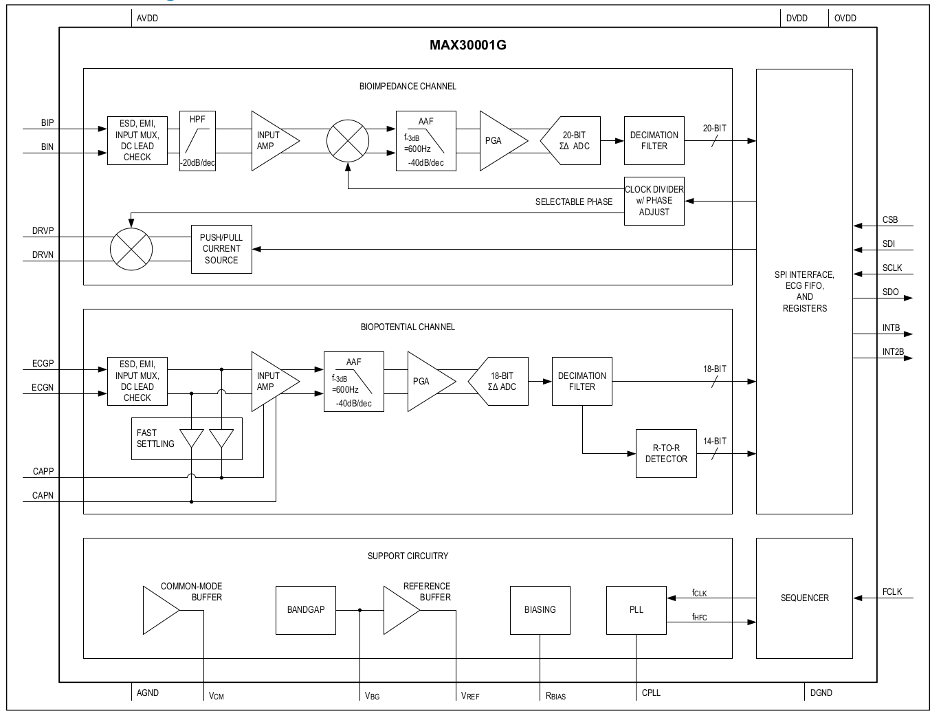
Block Diagram of MAX 30001G
The MAX30001G is a highly integrated analog front end that consists of a differential ECG channel with optional right-leg drive. It employs standard high-pass and low-pass filters, an instrumentation amplifier, and an analog-to-digital converter.
The impedance unit consists of a current driver, analog high-pass filter, and phase-shifted demodulator to measure impedance from 128kHz down to 125Hz modulation frequency at varying phase shifts. Internal-BIST validation shows coherent full-spectrum scans with dynamic AHPF selection, but the low-frequency end still rolls off below about 1kHz and external known-load validation is still required for production scan calibration.
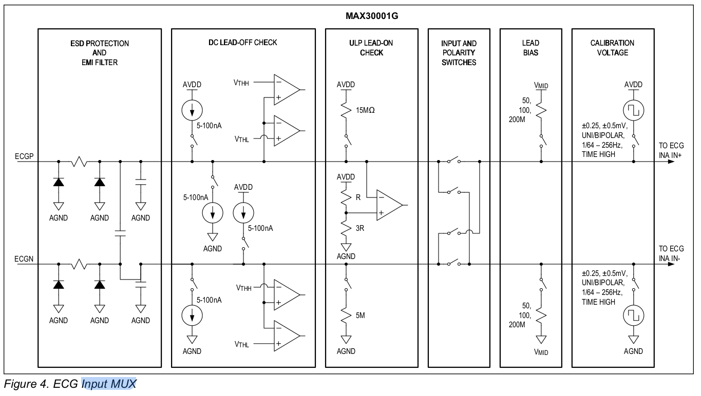
Input MUX ECG
Besides ESD protection, the input MUX can detect lead-off and lead-on conditions. In addition, it can switch input electrode polarity and correct common-voltage bias on the subject. Input can be turned off and replaced with an internal signal generator for testing purposes.
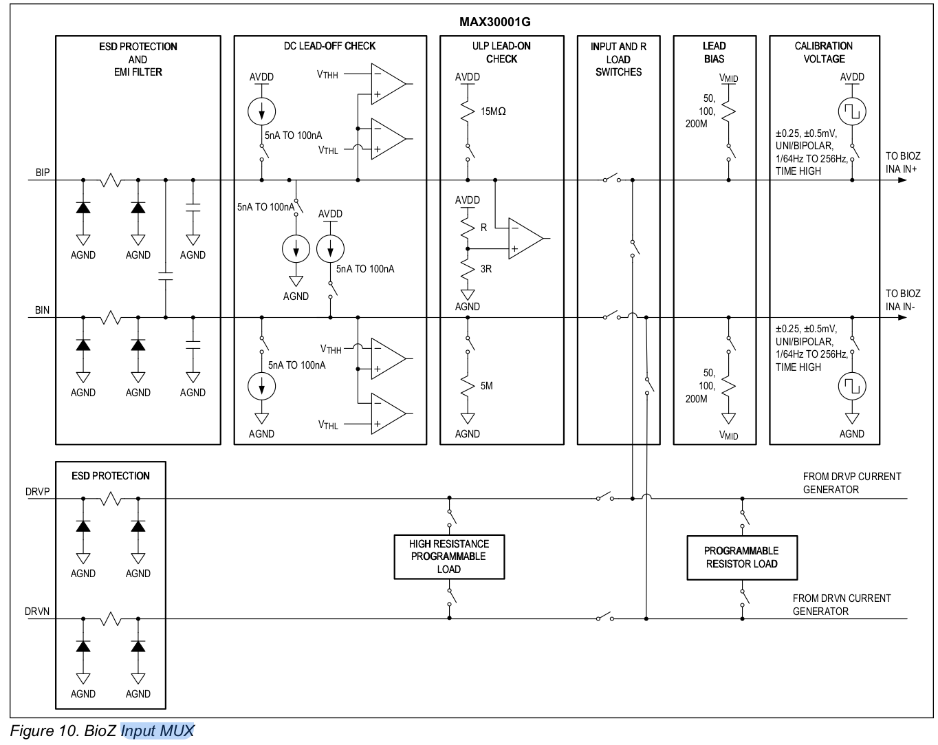
Input MUX BIOZ
Similar to the ECG input MUX, the BIOZ input MUX has ESD protection as well as lead-on and lead-off detection. Besides input signal calibration, a programmable resistor can be measured internally as simulated impedance.